- 您现在的位置:买卖IC网 > Sheet目录307 > ADE7761AARSZ-RL (Analog Devices Inc)IC ENERGY METERING 1PHASE 20SSOP
�� ��
��
��ADE7761A�
�APPLICATIONS�
�INTERFACING� TO� A� MICROCONTROLLER� FOR�
�ENERGY� MEASUREMENT�
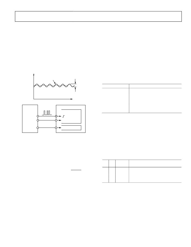
�The� easiest� way� to� interface� the� ADE7761A� to� a� microcontroller�
�is� to� use� the� CF� high� frequency� output� with� the� output� frequency�
�scaling� set� to� 2048� � F1,� F2.� This� is� done� by� setting� SCF� =� 0�
�and� S0� =� S1� =� 1� (see� Table� 8).� With� full-scale� ac� signals� on� the�
�analog� inputs,� the� output� frequency� on� CF� is� approximately�
�5.5� kHz.� Figure� 35� illustrates� one� scheme� that� could� be� used� to�
�digitize� the� output� frequency� and� carry� out� the� necessary�
�averaging� mentioned� in� the� Frequency� Output� CF� section.�
�CF�
�FREQUENCY�
�RIPPLE�
�SELECTING� A� FREQUENCY� FOR� AN� ENERGY�
�METER� APPLICATION�
�As� shown� in� Table� 6,� the� user� can� select� one� of� four� frequencies.�
�This� frequency� selection� determines� the� maximum� frequency�
�on� F1� and� F2.� These� outputs� are� intended� to� be� used� to� drive�
�the� energy� register� (electromechanical� or� other).� Because� only�
�four� different� output� frequencies� can� be� selected,� the� available�
�frequency� selection� was� optimized� for� a� meter� constant� of�
�100� impulses/kWh� with� a� maximum� current� of� between� 10� A�
�and� 120� A.� Table� 9� shows� the� output� frequency� for� several�
�maximum� currents� (I� MAX� )� with� a� line� voltage� of� 240� V.� In� all�
�cases,� the� meter� constant� is� 100� impulses/kWh.�
�Table� 9.� F1� and� F2� Frequency� at� 100� Impulses/kWh�
�AVERAGE�
�FREQUENCY�
�ADE7761A�
�TIME�
�MCU�
�COUNTER�
�±10%�
�I� MAX� (A)�
�12.5�
�25�
�40�
�60�
�80�
�120�
�F1� and� F2� (Hz)�
�0.083�
�0.166�
�0.266�
�0.4�
�0.533�
�0.8�
�CF�
�REVP� 1�
�FAULT� 2�
�UP/DOWN�
�LOGIC�
�The� F� 1–4� frequencies� allow� complete� coverage� of� this� range� of�
�output� frequencies� on� F1� and� F2.� When� designing� an� energy�
�meter,� the� nominal� design� voltage� on� Channel� 2� (voltage)�
�should� be� set� to� half-scale� to� allow� for� calibration� of� the� meter�
�constant.� The� current� channel� should� also� be� no� more� than� half-�
�1� REVP� MUST� BE� USED� IF� THE� METER� IS� BIDIRECTIONAL� OR�
�DIRECTION� OF� ENERGY� FLOW� IS� NEEDED.�
�2� FAULT� MUST� BE� USED� TO� RECORD� ENERGY� IN� FAULT� CONDITION.�
�Figure� 35.� Interfacing� the� ADE7761A� to� an� MCU�
�As� shown� in� Figure� 35� the� frequency� output� CF� is� connected� to�
�an� MCU� counter� or� port,� which� counts� the� number� of� pulses� in�
�a� given� integration� time,� determined� by� an� MCU� internal� timer.�
�scale� when� the� meter� sees� maximum� load,� which� accommodates�
�overcurrent� signals� and� signals� with� high� crest� factors.� Table� 10�
�shows� the� output� frequency� on� F1� and� F2� when� both� analog�
�inputs� are� half-scale.� The� frequencies� listed� in� Table� 10� align�
�well� with� those� listed� in� Table� 9� for� maximum� load.�
�Table� 10.� F1� and� F2� Frequency� with� Half-Scale� AC� Inputs�
�The� average� power,� proportional� to� the� average� frequency,� is�
�S0�
�S1�
�F� 1–4� (Hz)�
�Frequency� on� F1� and� F2,� Ch� 1� and� Ch� 2,�
�Half-Scale� AC� Inputs� (Hz)�
�Average� Frequency� =� Average� Active� Power� =�
�Counter�
�Timer�
�0�
�0�
�0�
�1�
�1.72�
�3.44�
�0.085�
�0.17�
�Energy� =� Average� Power� � Time� =�
�� Time� =� Counter�
�The� energy� consumed� during� an� integration� period� is�
�Counter�
�Time�
�For� the� purpose� of� calibration,� this� integration� time� could� be�
�10� sec� to� 20� sec� to� accumulate� enough� pulses� to� ensure� correct�
�averaging� of� the� frequency.� In� normal� operation,� the� integration�
�time� could� be� reduced� to� 1� sec� or� 2� sec� depending� on,� for�
�example,� the� required� update� rate� of� a� display.� With� shorter�
�integration� times� on� the� MCU,� the� amount� of� energy� in� each�
�update� may� still� have� a� small� amount� of� ripple,� even� under�
�1� 0� 6.86� 0.34�
�1� 1� 13.5� 0.68�
�When� selecting� a� suitable� F� 1–4� frequency� for� a� meter� design,� the�
�frequency� output� at� I� MAX� (maximum� load)� with� a� meter� constant�
�of� 100� impulses/kWh� should� be� compared� with� Column� 4� of�
�Table� 10.� The� frequency� that� is� closest� in� Table� 10� determines�
�the� best� choice� of� frequency� (F� 1-4� ).� For� example,� if� a� meter� with�
�a� maximum� current� of� 40� A� is� being� designed,� the� output�
�frequency� on� F1� and� F2� with� a� meter� constant� of� 100� impulses�
�per� kWh� is� 0.266� Hz� at� 40� A� and� 240� V� (see� Table� 9).�
�steady� load� conditions.� However,� over� a� minute� or� more,� the�
�measured� energy� has� no� ripple.�
�Rev.� 0� |� Page� 21� of� 24�
�发布紧急采购,3分钟左右您将得到回复。
相关PDF资料
ADE7761BARSZ-RL
IC ENERGY METERING 1PHASE 20SSOP
ADE7768ARZ-RL
IC ENERGY METERING 1PHASE 16SOIC
ADE7769ARZ-RL
IC ENERGY METERING 1PHASE 16SOIC
ADM8843ACPZ-REEL7
IC LED DRVR WHITE BCKLGT 16LFCSP
ADP1653ACPZ-R7
IC LED DRVR PHOTO FLASH 16-LFCSP
ADP1712-EVALZ
BOARD EVALUATION ADP1712
ADP1720-EVALZ
BOARD EVAL FOR ADP1720-ADJ
ADP2140CPZ-REDYKIT
REDYKIT 2 BOARDS ADP2140ACPZ
相关代理商/技术参数
ADE7761ARS
制造商:Rochester Electronics LLC 功能描述: 制造商:Analog Devices 功能描述:
ADE7761ARS-REF
制造商:Analog Devices 功能描述:ENERGY METER IC W/FAULT&MNEUT DETEC. - Bulk
ADE7761ARSRL
制造商:AD 制造商全称:Analog Devices 功能描述:Energy Metering IC with On-Chip Fault and Missing Neutral Detection
ADE7761B
制造商:AD 制造商全称:Analog Devices 功能描述:Energy Metering IC with On-Chip Fault and Missing Neutral Detection
ADE7761BARS
制造商:Rochester Electronics LLC 功能描述: 制造商:Analog Devices 功能描述:
ADE7761BARS-REF
制造商:AD 制造商全称:Analog Devices 功能描述:Energy Metering IC with On-Chip Fault and Missing Neutral Detection
ADE7761BARS-RL
制造商:AD 制造商全称:Analog Devices 功能描述:Energy Metering IC with On-Chip Fault and Missing Neutral Detection
ADE7761BARSZ
功能描述:IC ENERGY METERING 1PHASE 20SSOP RoHS:是 类别:集成电路 (IC) >> PMIC - 能量测量 系列:- 产品培训模块:Lead (SnPb) Finish for COTS
Obsolescence Mitigation Program 标准包装:2,500 系列:*